ANALYSIS OF CENTRIFUGAL BLOWER. The air flow moves along the centrifugal direction or radial direction.
Centrifugal Blowers What Is It How Does It Work Types
This pipe line connection is used to transport the waste from the machine to centralized blower.

. In this thesis the bower volute casing is designed to provide low volume high pressure air for cooling ventilating and exhaust system that handle dust materials or. Equal pressures around the blower casing and hence no radial thrust on the shaft. US20060165521A1 US11170113 US17011305A US2006165521A1 US 20060165521 A1 US20060165521 A1 US 20060165521A1 US 17011305 A US17011305 A US 17011305A US 2006165521 A1 US2006165521 A1 US 2006165521A1 Authority US United States Prior art.
The air enters the impeller in an axial direction and is discharged at the impeller outer periphery. This centrifugal blower can produce 20 in of wg 07396 psi and 2l2l ft3min 60 The flow direction of the liquid at the outlet of the m3min. Radial type centrifugal blower volute casing design for used in required industrial area.
Research the blower is designed air horsepower is 7 a. Design of Blower 5. The impeller the casing was concentric circular and it was made from brick while the wooden impeller was a backward straight blade.
Centrifugal fans consist of an impeller in a casing having a spirally shaped contour. When the fan rotates creates low pressure zone at the inlet thus intakes. This paper presents design of the -blade backward12 -curved impeller to be used in the centrifugal blower for 40 kW wood chips gasifier.
Rotary compressors physical design varies widely. The important geometrical parameters of volute are prioritized by applying first level of analytic hierarchy process. The 3D modeling of the blowers are created using SOLIDWORKS.
Classical fan and blower basic spiral casing design is based on a free vortex flow pattern and the assumption of a circumferentially uniform flow at the operating point where the flow rate through the impeller is equal to the flow rate through the spiral casing eg. In this research the blower is designed air 1 Radial perpendicular to inlet flow direction horsepower is 7 ahp 52 kW and the brake 2. We manufacture casings exclusively as a welded construction spiral casing with rectangular body shape.
To understand the typical design of centrifugal blower. Of air at 60 F and design speed 3450 rpm. Single-Stage Centrifugal Blowers Vortron Industrial specializes in the design and manufacture of high-performance high-efficiency centrifugal blowers for air knife systems and other applications.
One of the considerations that a designer should take is the proper design. The centrifugal fan uses the centrifugal power generated from the rotation of impellers to increase the pressure of airgases. The velocity achieved by the impeller transfers into pressure when the outward movement of the fluid is confined by the pump casing.
Google has not performed a legal analysis and makes no representation as to the accuracy of the status listed Expired - Lifetime Application number US346281A Inventor Karrer Josef. The rotor is set off-center so one side nearly touches the end of its casing which forces the vanes to move in as they approach this tight space. To study the various parts of centrifugal blower.
Fig 2Front Side View Of Centrifugal Blower 1. Based on the 2D drawings and data. After choosing the design data from catalogue the results of impeller inlet and outlet dimensions and vane angle could be obtained.
Performance reliability and cost-effectiveness are the main criteria in the design. In this paper various kinds of pumps and operational sequences are described. In 1826 Guido Bell from England invented the centrifugal blower.
The constant angle made by the volute with radial lines depends on the tangential to radial absolute velocity component ratio the volute casing is limited to operation efficiently at the fixed design point. Spiral casings for centrifugal fans and blowers are widely used in industry. Design Modification for weight optimization OBJECTIVE.
The performance of centrifugal blower is enhanced with an optimization process on the blower volute using Taguchi method and ANOVA approach. The simple design and structure of centrifugal blowers is the main reason for their popularity as well as their high endurance and reliability. As a result the gas pressure in the fan casing is increased.
If you compare air knife systems from. Scroll casing for centrifugal blowers Download PDF Info Publication number US20060165521A1. To optimize the load of the centrifugal blower impeller with the aid of using checking diverse substances like MS SS and SS316L.
However because the angle of the volute ie. Abstract- Impeller design plays an important role in manufacturing centrifugal blowers because without proper design the blowers cannot function effectively. Lets explore centrifugal fan or blower fan.
Spiral casing centrifugal blower casing diffusers Prior art date 1939-07-29 Legal status The legal status is an assumption and is not a legal conclusion. And then application and characteristics of centrifugal pump are also expressed. Analysis of blower impeller for unique cloth like MS SS SS316L etc.
All blowers and compressors are custom-designed by us. The analytic hierarchy process AHP is a structured technique for organizing and. Sometimes centrifugal fans are called radial flow type fans.
And a separate blower system with 5 HP motor fitted at one end of the plant. Centrifugal blowers are the most popular type of air movement tool used for industrial and commercial applications. Centrifugal blowers fans Design power Vane I.
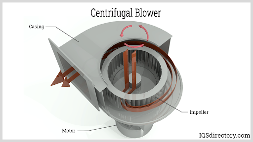
The design of centrifugal blowers includes a motor fan wheel and a housing. A well-designed centrifugal fan can decrease the probability of failure to a massive extent. The major parts of the blowers are fan inner diameter fan outer diameter blade inlet width blade outlet width number of blades blade thickness and volute casing.
Design is mainly focused for the single-stage. Machine constitute a third category. Vortron understands this concept better than anyone.
To lessen corrosion trouble of centrifugal blower. When the impellers rotate the gas near the impellers is thrown-off from the impellers due to the centrifugal force and then moves into the fan casing. Hp 52 kW and the brake horsepower is 10 b.
Centrifugal blower has three important parts namely fan volute casing and inlet duct. Centrifugal Blower design Premium components for efficient performance. This paper relates to the design of casing of single-suction centrifugal pump that can develop a head of 30m.
The key to a high-efficiency air knife system is a high-efficiency centrifugal blower. The motor is placed outside the casing and a shaft. Air circulation is among the core phenomena that keep massive importance.
The detailed design procedure for volute type pump casing is carried out.

Centrifugal Fan

Centrifugal Fan Design Calculations Xls Sante Blog Otosection
Schematic Diagram Of The Test Centrifugal Blower Download Scientific Diagram
2

Pdf Parametric Study Of Volutes For Optimal Centrifugal Fan Impellers Semantic Scholar

Pdf Design Of 5 Kw Radial Type Centrifugal Blower Casing Semantic Scholar

Pdf Design Of 5 Kw Radial Type Centrifugal Blower Casing Semantic Scholar
2
0 comments
Post a Comment